|
BEHRINGER B2 PRO
HISTORY and COMMENTS
|
I recently decided to buy a large-diaphragm condenser mic for my home studio. One option was to build a U87 clone using plans found online, it looked like a great project. But buying a mic shell and constructing a clone isn't exactly cheap. And finding a quality review of a clone's sound quality was oddly difficult. So I decided it would be more fun to modify a NEW microphone. After comparing specs and reviews I decided to use the Behringer B2 Pro. The B2 is passed over as a candidate for modding for some reason which is puzzling. It has switchable polar patterns, excellent specs, U87 look, and a great price. It was designed in the early 2000s using a mic circuit created by the company 797 Audio. Details are sketchy but I have read that 797 Audio Co. Ltd was originally founded in 1952 with the help of an unknown German company. On a side note, Behringer is a German company founded in 1989 but now makes all its products in "Behringer City" in Zhongshan.
STOCK CIRCUIT
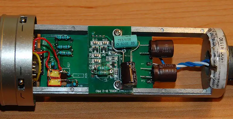
Despite the mystique, a microphone circuit-board is relatively simple not rocket science. Most are based on the "Shoeps" circuit and photos of the original B2 show several Wima capacitors and a handful of resistors and diodes. However when I opened up my new mic I was in for a surprise. It appears Behringer has moved from standard parts to SMD types (surface mount). SMD parts may not be as exciting as traditional ones. But benefits are lower noise, shorter signal paths, and less parasitic inductance from long leads. Compared to older photos this newer version contains twice as many parts as the original B2.
Unscrewing the base and sliding off the shell reveals the main board. With a gold-plated terminal pin connector it removes easily by taking out 2 screws and sliding it back.
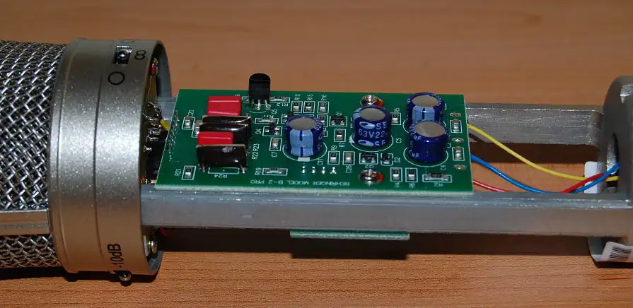 |
- The four blue electrolytics are Sanwha SE caps of 22uf/63V. Sanwha lists the SE as "standard models suitable to replace tantalums at low cost".
- There are three black no-name 51M ohm resistors. A single black Fairchild BF245A transistor is used for the diaphragm circuit. This transistor was listed as obsolete in 2012.
- Two 10% 1000pf Wima film caps are used. Both sit in a hole in the board with leads hanging out the bottom. The one connected to the capsule is a "1000/630V" and looks like a FKP2 (film/foil polypropylene). The one connected to the FET is a "1000/100V" and looks like a FKS2 (Polyethylene-terephthalate/PET) film.
- A third Wima cap is a 10% .015 250V which looks like a FKS2 (Polyethylene-terephthalate/PET) film.
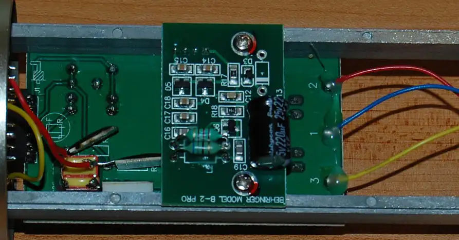
A view from the bottom shows the Wima pair and three black 1G ohm resistors. One Wima is soldered to a FET lead that passes through a hole in the board: this isolates the FET leg from the PCB and solder traces to reduce noise. The two green "resistors" are actually inductors of 220mh and 68mh at 5%. The electrolytic cap is a 220uf 25v Rubycon XYF which is listed as a "105C, long life, low impedance" type.
 |
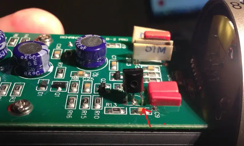
BELOW
I noticed something surprising. The leg of the FET passing though the PCB to a 1G ohm resistor was touching the edge of the circuit board (fixed for the photo). This is a big no-no as touching the board increases circuit noise which defeats the point of isolating the connection in mid-air. I used a small screwdriver to carefully pry the leg away to center it in the hole. Behringer should pay more attention to this during production.
 |
THE MOD
Swapping out the blue electrolytics was my first task but replacement choices were limited. Tantalum capacitors are classed as electrolytics and have been used in microphones for decades because of their tiny size. However despite their long history by modern standards they are considered sonically inferior and obsolete. Tantalum is also a conflict mineral, so I don't feel comfortable them using them even in a vintage restoration. Modern film caps are too large meaning the only choice for coupling caps are tiny audio-grade electrolytics. 21st century choices are the Elna Silmic and the Nichicon KZ which are specifically designed for sound quality. The Silmics have pages of forum comments describing their sound, yet the KZs have fewer despite being known to the audiophile community since the mid 1990s.
I didn't want obsess over which was better. But when dealing with microvolt input signals subtle differences between caps are going to appear. Bright vs tube-like, etched vs smooth, which is correct? To my ears the Silmics are dynamically correct with 'body' and realistic bass. The KZs had a clean, natural presentation but I found them slightly leaner tonally and a bit polite. I decided on a combo of the two. NOTE: the boards have plated-through holes and thin tracing on both sides, care must be taken when de-soldering so as not to pull the traces from the holes or board.
- I had to bend over one 22uf/50V Nichicon KZ to reach the solder joint. The lower pair were too tall so I relocated them to the bottom of the board.
- I changed the two 1000pf caps to Wima FKP2 1000pf/100V 2.5% (film/foil polypropylene). I replaced the Wima .015 with a .015 1% Wima FKP2
- The 220uf/25V electrolyic was a low impedance cap from the factory so I decided against an audio-grade electrolytic. I replaced it with a Nichicon PW (low impedance, high reliability, for switching power supplies). I also added a .22uf Russian K73-11 PETP bypass.
- I replaced the three 1G ohm resistors with Ohmite MOX-200001007JE 1G ohm 5% versions which are rated for "Avionics, medical electronics, high gain feedback applications, current pulse limiters, vacuum and space application". I also replaced the three 51M ohm resistors with 50M Ohmite MOX-200005005FE 1% versions (I installed them on the bottom of the board because of crowding).
- The factory had filled up the XLR connector with hot glue and put dabs in the wire solder joints on the board. I removed all the old hot glue and replaced the three wires from the XLR to the circuit board with stands of 21g Canare L-4E6S wire.
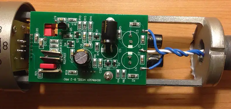 |
TOP PHOTO - the original 51M ohm resistors before moving tkem beneath the board.
BOTTOM PHOTO - the new 51M and 1G ohm Ohmite resistors are on the top left.
|
 |
CONCLUSION: Behringer should double-check the FET leg/board clearance at the factory, remove the hot glue from the XLR and solder joints to prevent bleed-over, and float the circuit by not using the XLR ground lug. All cost nothing and increase performance.
A decade ago it was commented online that Chinese mics needed to EQ their circuits to tone down the slight brightness of the capsules they used. This new generation B2 is said to use a custom-made capsule, and taking into account the redesigned SMD circuit boards and gold-pin connectors it appears Behringer has consciously updated the older design. The final clarity and low noise of this sub $200 microphone with $20 of tweaks was beyond what I expected. I am very pleased and satisfied.
Click on the links below to play my 44khz 24-bit tests |
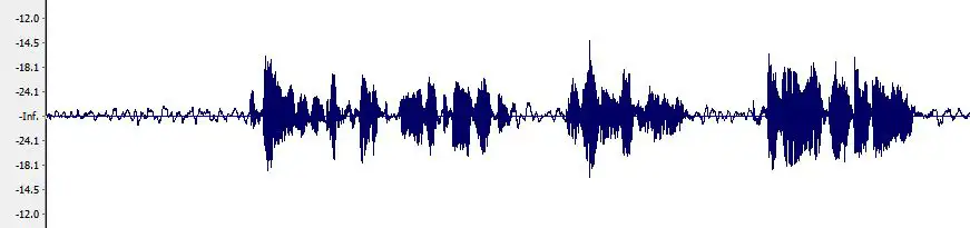
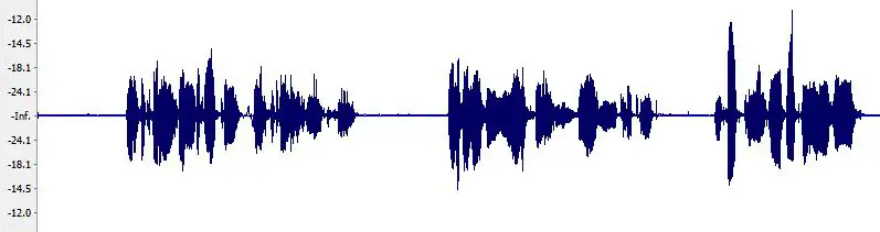
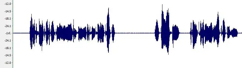
The noise floor between stock and modified circuits is audible and visible. NOTE: to hear the details use sensitive headphones.
<
Datsunzgarage.us © 1997-2026
All mods are illustrative only, perform at your own risk.
Datsun is a registered trademark of Nissan®