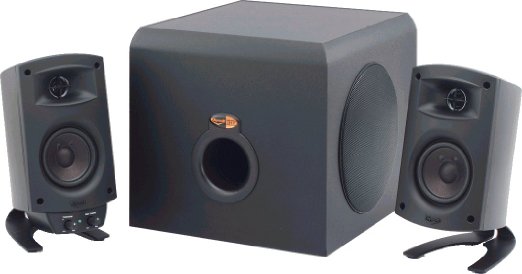
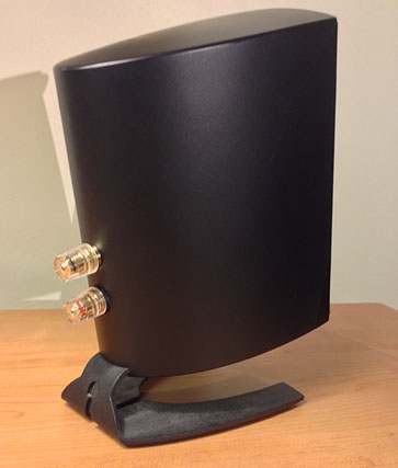
KLIPSCH PROMEDIA 2.1
HISTORY and COMMENTS
|
I bought this audio system back in 1999 for my home PC. Now after 20+ years, seeing that Klipsch still produces this THX-rated system implies its a pretty solid design. But I suspected some parts were tired and might need replacing. This made it a perfect candidate to open up to modify.
NOTE: For the old models the schematic states a Class D amplifier was used for the woofer and separate Class A/B amplifier for the satellites. Mine contains a large transformer but I have noticed that more recent versions of the Promedia have smaller boards with tiny transformers. Today, I suspect highly efficient Class D amplifiers are being used throughout.
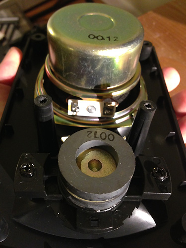
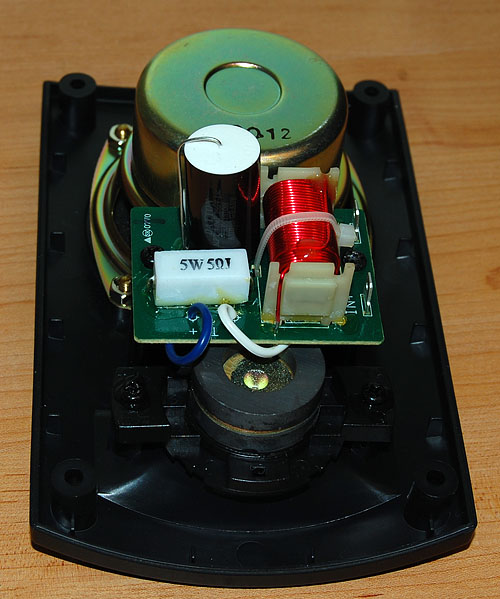
The first step in any mod is to open it up and see what's inside. What I found inside the speakers was surprising. Instead of a set of cheap drivers in a box Klipsch actually made the satellites into
real speakers. The cabinets contained white fiber-fill, and the crossovers have a 6db slope with higher quality parts than I've seen in some floor speakers.
Good job Klipsch!
A generic "CAPEX" 4uf 100v NP electrolytic cap is used on the tweeter. While this cap isn't audiophile quality for a small computer speaker it's acceptable. However, I measured them at 4.75 and 4.83uf which is close to 20% out of tolerance, not good. A 5 ohm 5W resistor pads the tweeter. An iron-core inductor is used on the mid-woofer.
|
|
The mid-woofer is fairly robust with a foam surround and a long-throw magnet. The heavy, dual-magnet design is unusual for a tweeter, especially in a speaker meant to receive only 35 watts max. This "overdesign" is an unexpected but welcome sight.
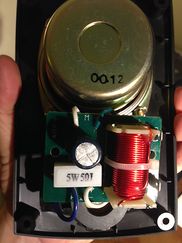
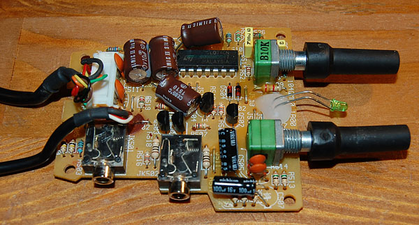
BELOW: the Control Pod beneath one speaker is removable and slides back to come out with a bit of fiddling. Inside are some electrolytics just
begging to be changed out. The four on the top left are 10uf 50v polarized caps which if you look at the schematic are the input caps for each channel. In a peculiar move they are wired as reversed pairs to create 20uf non-polar caps. A NP cap is actually two polarized caps reversed
inside a case...but this is the first time I've ever seen separate pairs soldered this way. I'm guessing it was for space considerations. The other two caps are 100uf 16V. A TLO74CN low-noise JFET op amp and assorted resistors, diodes, etc, round things out.
NOTE: If you follow the circuit, the musical signal from the PC first travels to the Control Pod under the speaker... through the "20uf" NP input cap circuit...back down to the sub...to the HF amplifier inside the sub...then out the speaker jacks to the satellites. This means optimizing the Control Pod circuit will have an audible effect on the sound quality.
2ND NOTE: using speaker spring-clips on the back of the sub where they can be easily kicked loose is a poor design. As with stereo receivers, it's common for exposed speaker wire ends not to be pushed in all the way...and easily short the wire next to it. I suspect this is where many reports of these subs being unreliable came from.
THE MOD
The mini-pin input on the back of the speaker is not a good choice for a speaker rated for 35 watts. In fact, if you own this system you are likely familiar with having to fiddle with the mini-pin on the speaker every time it cuts out. Others who have modded this speaker came to the same conclusion: replace it with a pair of binding posts...so I bought an inexpensive set of "mini" binding posts online from Parts Express.
The existing mini-pin is easily removable from the inside of the cabinet. Minus all the extra collars and plastic base the new metal binding post fit
perfectly into the existing hole. I then measured and carefully drilled a hole for the upper post, using one of the new binding post collars to insert in the hole from the inside for strength. The result are two posts that appear "factory" and sit the same height. Think this through before you drill, as you can't drill a hole smaller(!)
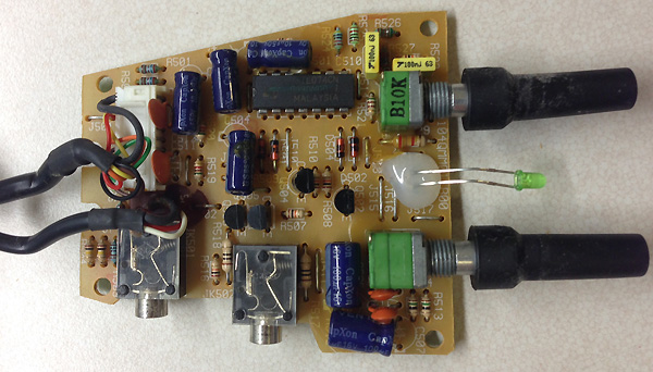
Next I replaced the input caps on the Control Pod with 10uf 50V Elna Silmics. I find Silmics to have a smooth, open sound with accurate bass. Slightly large but they fit fine.
Due to space limitations I changed the two 100uf next to the bass pot with Nichicon VRs. VR's are quality general purpose caps with neutral sonic character and are excellent in modern circuits.
BELOW: Now this is a great looking crossover. I replaced the electrolytic on the tweeter with a Dayton 1% 4uf 250V metallized polypropylene. I have used the Daytons over the years and find them to have a clear, accurate sound with no hyper detail...very musical. I left the resistor and inductor alone.
SUBWOOFER MUFFLED SOUND ISSUE
After the mods above I didn't use the system for about a year and when I powered it up the satellites sounded fine but there was low muffled bass coming out the sub.
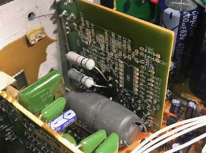
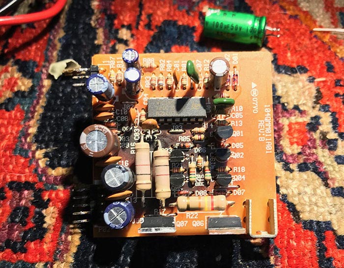
The cause is well-known and is due to a pair of resistors on the subwoofer board overheating over the years and melting their solder joints...burning the board in the process. The resistors are situated above the board in a standard practice to aid in cooling...which apparently doesnt work well. My Promedia is an "early" unit and has pair of 800 ohm 5% in these spots.
They measured about 913 ohms which is 15% out of spec.
To remove the board I had to unsolder its pins from the board next to it. While I had it out I replaced the electrolytic caps with either Elna Silmics or Nichicon VRs depending on what would fit (same values).
| |
 |
|
BELOW: According to the online schematic later version Promedias received 1K 2 watt resistors in this spot. With little to lose I followed Klipsch' lead and replaced my 800 ohm with
1K Xicon 2W metal oxide resistors. To remove heat from the componant side of the board I relocated them to the foil side. Rather than removing the board this can be done by clipping off the old resistors and soldering new ones like below.
CONCLUSION: after all the mods to the speaker and control pod the sound quality has definitely changed. Music is much more open with a detailed 'presence' that didn't exist before. Imaging is now rock solid with vocals hanging in 3D space between the speakers...an actual soundstage exists. Transients and guitar zips are more detailed and bass is tighter and more integrated with the music. The sound is simply, better.
Fixing the resistors on the subwoofer board restored the punchy, deep bass I was familiar with on this unit. This was a fun project.
Datsunzgarage.us © 1997-2026
All mods are illustrative only, perform at your own risk.
Datsun is a registered trademark of Nissan®